Visible to Intel only — GUID: jkx1613473073764
Ixiasoft
Answers to Top FAQs
1. About DSP Builder for Intel® FPGAs
2. DSP Builder for Intel FPGAs Advanced Blockset Getting Started
3. DSP Builder Design Flow
4. Primitive Library Blocks Tutorial
5. IP Tutorial
6. DSP Builder for Intel FPGAs (Advanced Blockset) Design Examples and Reference Designs
7. DSP Builder Design Rules, Design Recommendations, and Troubleshooting
8. About DSP Builder for Intel FPGAs Optimization
9. About Folding
10. Floating-Point Data Types
11. Design Configuration Library
12. IP Library
13. Interfaces Library
14. Primitives Library
15. Utilities Library
16. Simulink Supported Blocks
17. Document Revision History for DSP Builder for Intel FPGAs (Advanced Blockset) Handbook
1.1. DSP Builder for Intel® FPGAs Features
1.2. DSP Builder for Intel® FPGAs Design Structure
1.3. DSP Builder for Intel® FPGAs Libraries
1.4. DSP Builder for Intel® FPGAs Device Support
1.5. FPGA Architecture Features for DSP Designs
1.6. DSP Design Flow in FPGAs
1.7. Software and Hardware DSP Design Flows in FPGAs
2.1. System Requirements
2.2. Installing DSP Builder for Intel® FPGAs
2.3. Licensing DSP Builder for Intel® FPGAs
2.4. Starting DSP Builder in MATLAB on Windows
2.5. Starting DSP Builder in MATLAB on Linux
2.6. Browsing DSP Builder Libraries and Adding Blocks to a New Model
2.7. Browsing and Opening DSP Builder Design Examples
2.8. Creating a New DSP Builder Design with the DSP Builder New Model Wizard
2.9. Simulating, Verifying, Generating, and Compiling Your DSP Builder Design
3.1. Implementing your Design in DSP Builder Advanced Blockset
3.2. Verifying your DSP Builder Advanced Blockset Design in Simulink and MATLAB
3.3. Exploring DSP Builder Advanced Blockset Design Tradeoffs
3.4. Verifying your DSP Builder Design with C++ Software Models
3.5. Verifying your DSP Builder Advanced Blockset Design in the ModelSim Simulator
3.6. Verifying Your DSP Builder Design in Hardware
3.7. Integrating Your DSP Builder Advanced Blockset Design into Hardware
3.1.2.1. DSP Builder Block Interface Signals
3.1.2.2. Periods
3.1.2.3. Sample Rate
3.1.2.4. Building Multichannel Systems
3.1.2.5. Channelization for Two Channels with a Folding Factor of 3
3.1.2.6. Channelization for Four Channels with a Folding Factor of 3
3.1.2.7. Synchronization and Scheduling of Data with the Channel Signal
3.1.2.8. Simulink vs Hardware Design Representations
3.2.1. Verifying your DSP Builder Advanced Blockset Design with a Testbench
3.2.2. Running DSP Builder Advanced Blockset Automatic Testbenches
3.2.3. Using DSP Builder Advanced Blockset References
3.2.4. Setting Up Stimulus in DSP Builder Advanced Blockset
3.2.5. Analyzing your DSP Builder Advanced Blockset Design
4.1. Creating a Fibonacci Design from the DSP Builder Primitive Library
4.2. Setting the Parameters on the Testbench Source Blocks
4.3. Simulating the Fibonacci Design in Simulink
4.4. Modifying the DSP Builder Fibonacci Design to Generate Vector Signals
4.5. Simulating the RTL of the Fibonacci Design
5.1. Creating an IP Design
5.2. Simulating the IP Design in Simulink
5.3. Viewing Timing Closure and Viewing Resource Utilization for the DSP Builder IP Design
5.4. Reparameterizing the DSP Builder FIR Filter to Double the Number of Channels
5.5. Doubling the Target Clock Rate for a DSP Builder IP Design
6.1. DSP Builder Design Configuration Block Design Examples
6.2. DSP Builder FFT Design Examples
6.3. DSP Builder DDC Design Example
6.4. DSP Builder Filter Design Examples
6.5. DSP Builder Finite State Machine Design Example
6.6. DSP Builder Folding Design Examples
6.7. DSP Builder Floating Point Design Examples
6.8. DSP Builder Flow Control Design Examples
6.9. DSP Builder HDL Import Design Example
6.10. DSP Builder Host Interface Design Examples
6.11. DSP Builder Fixed-Point Matrix Multiply Engine Design Example
6.12. DSP Builder Platform Design Examples
6.13. DSP Builder Primitive Block Design Examples
6.14. DSP Builder Reference Designs
6.15. DSP Builder Waveform Synthesis Design Examples
6.2.1. FFT
6.2.2. FFT without BitReverseCoreC Block
6.2.3. IFFT
6.2.4. IFFT without BitReverseCoreC Block
6.2.5. Floating-Point FFT
6.2.6. Floating-Point FFT without BitReverseCoreC Block
6.2.7. Floating-Point iFFT
6.2.8. Floating-Point iFFT without BitReverseCoreC Block
6.2.9. Multichannel FFT
6.2.10. Multiwire Transpose
6.2.11. Parallel FFT
6.2.12. Parallel Floating-Point FFT
6.2.13. Single-Wire Transpose
6.2.14. Switchable FFT/iFFT
6.2.15. Variable-Size Fixed-Point FFT
6.2.16. Variable-Size Fixed-Point FFT without BitReverseCoreC Block
6.2.17. Variable-Size Fixed-Point iFFT
6.2.18. Variable-Size Fixed-Point iFFT without BitReverseCoreC Block
6.2.19. Variable-Size Floating-Point FFT
6.2.20. Variable-Size Floating-Point FFT without BitReverseCoreC Block
6.2.21. Variable-Size Floating-Point iFFT
6.2.22. Variable-Size Floating-Point iFFT without BitReverseCoreC Block
6.2.23. Variable-Size Low-Resource FFT
6.2.24. Variable-Size Low-Resource Real-Time FFT
6.2.25. Variable-Size Supersampled FFT
6.2.26. Variable-Size Supersampled FFT with Bit-Reverse
6.4.1. Complex FIR Filter
6.4.2. Decimating CIC Filter
6.4.3. Decimating FIR Filter
6.4.4. Filter Chain with Forward Flow Control
6.4.5. FIR Filter with Exposed Bus
6.4.6. Fractional FIR Filter Chain
6.4.7. Fractional-Rate FIR Filter
6.4.8. Half-Band FIR Filter
6.4.9. IIR: Full-rate Fixed-point
6.4.10. IIR: Full-rate Floating-point
6.4.11. Interpolating CIC Filter
6.4.12. Interpolating FIR Filter
6.4.13. Interpolating FIR Filter with Multiple Coefficient Banks
6.4.14. Interpolating FIR Filter with Updating Coefficient Banks
6.4.15. Root-Raised Cosine FIR Filter
6.4.16. Single-Rate FIR Filter
6.4.17. Super-Sample Decimating FIR Filter
6.4.18. Super-Sample Fractional FIR Filter
6.4.19. Super-Sample Interpolating FIR Filter
6.4.20. Variable-Rate CIC Filter
6.7.1. Black-Scholes Floating Point
6.7.2. Double-Precision Real Floating-Point Matrix Multiply
6.7.3. Fine Doppler Estimator
6.7.4. Floating-Point Mandlebrot Set
6.7.5. General Real Matrix Multiply One Cycle Per Output
6.7.6. Newton Root Finding Tutorial Step 1—Iteration
6.7.7. Newton Root Finding Tutorial Step 2—Convergence
6.7.8. Newton Root Finding Tutorial Step 3—Valid
6.7.9. Newton Root Finding Tutorial Step 4—Control
6.7.10. Newton Root Finding Tutorial Step 5—Final
6.7.11. Normalizer
6.7.12. Single-Precision Complex Floating-Point Matrix Multiply
6.7.13. Single-Precision Real Floating-Point Matrix Multiply
6.7.14. Simple Nonadaptive 2D Beamformer
6.8.1. Avalon-ST Interface (Input and Output FIFO Buffer) with Backpressure
6.8.2. Avalon-ST Interface (Output FIFO Buffer) with Backpressure
6.8.3. Kronecker Tensor Product
6.8.4. Parallel Loops
6.8.5. Primitive FIR with Back Pressure
6.8.6. Primitive FIR with Forward Pressure
6.8.7. Primitive Systolic FIR with Forward Flow Control
6.8.8. Rectangular Nested Loop
6.8.9. Sequential Loops
6.8.10. Triangular Nested Loop
6.13.1. 8×8 Inverse Discrete Cosine Transform
6.13.2. Automatic Gain Control
6.13.3. Bit Combine for Boolean Vectors
6.13.4. Bit Extract for Boolean Vectors
6.13.5. Color Space Converter
6.13.6. CORDIC from Primitive Blocks
6.13.7. Digital Predistortion Forward Path
6.13.8. Fibonacci Series
6.13.9. Folded Vector Sort
6.13.10. Fractional Square Root Using CORDIC
6.13.11. Fixed-point Maths Functions
6.13.12. Gaussian Random Number Generator
6.13.13. Hello World
6.13.14. Hybrid Direct Form and Transpose Form FIR Filter
6.13.15. Loadable Counter
6.13.16. Matrix Initialization of LUT
6.13.17. Matrix Initialization of Vector Memories
6.13.18. Multichannel IIR Filter
6.13.19. Quadrature Amplitude Modulation
6.13.20. Reinterpret Cast for Bit Packing and Unpacking
6.13.21. Run-time Configurable Decimating and Interpolating Half-Rate FIR Filter
6.13.22. Square Root Using CORDIC
6.13.23. Test CORDIC Functions with the CORDIC Block
6.13.24. Uniform Random Number Generator
6.13.25. Vector Sort—Sequential
6.13.26. Vector Sort—Iterative
6.13.27. Vector Initialization of Sample Delay
6.13.28. Wide Single-Channel Accumulators
6.14.1. 1-Antenna WiMAX DDC
6.14.2. 2-Antenna WiMAX DDC
6.14.3. 1-Antenna WiMAX DUC
6.14.4. 2-Antenna WiMAX DUC
6.14.5. 4-Carrier, 2-Antenna W-CDMA DDC
6.14.6. 1-Carrier, 2-Antenna W-CDMA DDC
6.14.7. 4-Carrier, 2-Antenna W-CDMA DUC
6.14.8. 4-Carrier, 4-Antenna DUC and DDC for LTE
6.14.9. 1-Carrier, 2-Antenna W-CDMA DDC
6.14.10. 4-Carrier, 2-Antenna High-Speed W-CDMA DUC at 368.64 MHz with Total Rate Change 32
6.14.11. 4-Carrier, 2-Antenna High-Speed W-CDMA DUC at 368.64 MHz with Total Rate Change 48
6.14.12. 4-Carrier, 2-Antenna High-Speed W-CDMA DUC at 307.2 MHz with Total Rate Change 40
6.14.13. Cholesky-based Matrix Inversion
6.14.14. Cholesky Solver Multiple Channels
6.14.15. Crest Factor Reduction
6.14.16. Direct RF with Synthesizable Testbench
6.14.17. Dynamic Decimating FIR Filter
6.14.18. Multichannel QR Decompostion
6.14.19. QR Decompostion
6.14.20. QRD Solver
6.14.21. Reconfigurable Decimation Filter
6.14.22. Single-Channel 10-MHz LTE Transmitter
6.14.23. STAP Radar Forward and Backward Substitution
6.14.24. STAP Radar Steering Generation
6.14.25. STAP Radar QR Decomposition 192x204
6.14.26. Time Delay Beamformer
6.14.27. Transmit and Receive Modem
6.14.28. Variable Integer Rate Decimation Filter
8.1. Associating DSP Builder with MATLAB
8.2. Setting Up Simulink for DSP Builder Designs
8.3. The DSP Builder Windows Shortcut
8.4. Setting DSP Builder Design Parameters with MATLAB Scripts
8.5. Managing your Designs
8.6. How to Manage Latency
8.7. Flow Control in DSP Builder Designs
8.8. Reset Minimization
8.9. About Importing HDL
10.1. DSP Builder Floating-Point Data Type Features
10.2. DSP Builder Supported Floating-Point Data Types
10.3. DSP Builder Round-Off Errors
10.4. Trading Off Logic Utilization and Accuracy in DSP Builder Designs
10.5. Upgrading Pre v14.0 Designs
10.6. Floating-Point Sine Wave Generator Tutorial
10.7. Newton-Raphson Root Finding Tutorial
10.8. Forcing Soft Floating-point Data Types with the Advanced Options
12.1.1. DSP Builder FIR and CIC Filters
12.1.2. DSP Builder FIR Filters
12.1.3. Channel Viewer (ChanView)
12.1.4. Complex Mixer (ComplexMixer)
12.1.5. Decimating CIC
12.1.6. Decimating FIR
12.1.7. Fractional Rate FIR
12.1.8. Interpolating CIC
12.1.9. Interpolating FIR
12.1.10. NCO
12.1.11. Real Mixer (Mixer)
12.1.12. Scale
12.1.13. Single-Rate FIR
13.1.1. Bus Slave (BusSlave)
13.1.2. Bus Stimulus (BusStimulus)
13.1.3. Bus Stimulus File Reader (Bus StimulusFileReader)
13.1.4. External Memory, Memory Read, Memory Write
13.1.5. Register Bit (RegBit)
13.1.6. Register Field (RegField)
13.1.7. Register Out (RegOut)
13.1.8. Shared Memory (SharedMem)
14.3.1. About Pruning and Twiddle for FFT Blocks
14.3.2. Bit Vector Combine (BitVectorCombine)
14.3.3. Butterfly Unit (BFU)
14.3.4. Butterfly I C (BFIC) (Deprecated)
14.3.5. Butterfly II C (BFIIC) (Deprecated)
14.3.6. Choose Bits (ChooseBits)
14.3.7. Crossover Switch (XSwitch)
14.3.8. Dual Twiddle Memory (DualTwiddleMemoryC)
14.3.9. Edge Detect (EdgeDetect)
14.3.10. Floating-Point Twiddle Generator (TwiddleGenF) (Deprecated)
14.3.11. Fully-Parallel FFTs (FFT2P, FFT4P, FFT8P, FFT16P, FFT32P, and FFT64P)
14.3.12. Fully-Parallel FFTs with Flexible Ordering (FFT2X, FFT4X, FFT8X, FFT16X, FFT32X, and FFT64X)
14.3.13. General Multitwiddle and General Twiddle (GeneralMultiTwiddle, GeneralMultVTwiddle, GeneralTwiddle, GeneralVTwiddle)
14.3.14. Hybrid FFT (Hybrid_FFT, HybridVFFT, HybridVFFT_btb)
14.3.15. Multiwire Transpose (MultiwireTranspose)
14.3.16. Multiwire Variable Bit Reverse (MultiwireVariableBitReverse)
14.3.17. Parallel Pipelined FFT (PFFT_Pipe)
14.3.18. Pulse Divider (PulseDivider)
14.3.19. Pulse Multiplier (PulseMultiplier)
14.3.20. Single-Wire Transpose (Transpose)
14.3.21. Split Scalar (SplitScalar)
14.3.22. Streaming FFTs (FFT2, FFT4, VFFT2, and VFFT4)
14.3.23. Stretch Pulse (StretchPulse)
14.3.24. Twiddle Angle (TwiddleAngle)
14.3.25. Twiddle Generator (TwiddleGenC) Deprecated
14.3.26. Twiddle and Variable Twiddle (Twiddle and VTwiddle)
14.3.27. Twiddle ROM (TwiddleRom, TwiddleMultRom and TwiddleRomF (deprecated))
14.4.1. Absolute Value (Abs)
14.4.2. Accumulator (Acc)
14.4.3. Add
14.4.4. Add SLoad (AddSLoad)
14.4.5. AddSub
14.4.6. AddSubFused
14.4.7. AND Gate (And)
14.4.8. Bit Combine (BitCombine)
14.4.9. Bit Extract (BitExtract)
14.4.10. Bit Reverse (BitReverse)
14.4.11. Compare (CmpCtrl)
14.4.12. Complex Conjugate (ComplexConjugate)
14.4.13. Compare Equality (CmpEQ)
14.4.14. Compare Greater Than (CmpGE)
14.4.15. Compare Less Than (CmpLT)
14.4.16. Compare Not Equal (CmpNE)
14.4.17. Constant (Const)
14.4.18. Constant Multiply (Const Mult)
14.4.19. Convert
14.4.20. CORDIC
14.4.21. Counter
14.4.22. Count Leading Zeros, Ones, or Sign Bits (CLZ)
14.4.23. Dual Memory (DualMem)
14.4.24. Demultiplexer (Demux)
14.4.25. Divide
14.4.26. Fanout
14.4.27. FIFO
14.4.28. Floating-point Classifier (FloatClass)
14.4.29. Floating-point Multiply Accumulate (MultAcc)
14.4.30. ForLoop
14.4.31. Load Exponent (LdExp)
14.4.32. Left Shift (LShift)
14.4.33. Loadable Counter (LoadableCounter)
14.4.34. Look-Up Table (Lut)
14.4.35. Loop
14.4.36. Math
14.4.37. Minimum and Maximum (MinMax)
14.4.38. MinMaxCtrl
14.4.39. Multiply (Mult)
14.4.40. Multiplexer (Mux)
14.4.41. NAND Gate (Nand)
14.4.42. Negate
14.4.43. NOR Gate (Nor)
14.4.44. NOT Gate (Not)
14.4.45. OR Gate (Or)
14.4.46. Polynomial
14.4.47. Ready
14.4.48. Reinterpret Cast (ReinterpretCast)
14.4.49. Round
14.4.50. Sample Delay (SampleDelay)
14.4.51. Scalar Product
14.4.52. Select
14.4.53. Sequence
14.4.54. Shift
14.4.55. Sqrt
14.4.56. Subtract (Sub)
14.4.57. Sum of Elements (SumOfElements)
14.4.58. Trig
14.4.59. XNOR Gate (Xnor)
14.4.60. XOR Gate (Xor)
14.6.1. Anchored Delay
14.6.2. Complex to Real-Imag
14.6.3. Enabled Delay Line
14.6.4. Enabled Feedback Delay
14.6.5. Expand Scalar (ExpandScalar)
14.6.6. Finite State Machine
FSM Specification Language
Options
Netlist Components
State Transitions
State Transition Diagram
ForLoop Blocks
Nested ForLoops
Strategies for Hiding Dead Cycles
14.6.7. Nested Loops (NestedLoop1, NestedLoop2, NestedLoop3)
14.6.8. Pause
14.6.9. Reset-Priority Latch (SRlatch_PS)
14.6.10. Same Data Type (SameDT)
14.6.11. Set-Priority Latch (SRlatch)
14.6.12. Single-Cycle Latency Latch (latch_1L)
14.6.13. Tapped Line Delay (TappedLineDelay)
14.6.14. Variable Super-Sample Delay (VariableDelay)
14.6.15. Vector Fanout (VectorFanout)
14.6.16. Vector Multiplexer (VectorMux)
14.6.17. Zero-Latency Latch (latch_0L)
FSM Specification Language
Options
Netlist Components
State Transitions
State Transition Diagram
ForLoop Blocks
Nested ForLoops
Strategies for Hiding Dead Cycles
14.6.6.1. Adding a Finite State Machine Block to your DSP Builder Design
14.6.6.2. Modifying the Finite State Machine Block Specification File
14.6.6.3. Implement Token Passing with the Finite State Machine
14.6.6.4. Implementing a One Shot Counter with the Finite State Machine
14.6.6.5. Specifying ForLoop Control Units
14.6.6.6. Creating the Finite State Machine Configuration File
14.6.6.7. Upgrading Finite State Machine Blocks from v23.2 and Earlier
Visible to Intel only — GUID: jkx1613473073764
Ixiasoft
14.6.6. Finite State Machine
The Finite State Machine block adds state machines to a DSP Builder design. You can describe your Finite State Machine using the FSM specification language, which you enter into a text file. Then you load that text file using the Finite State Machine block and wire up the input and output ports of the Finite State Machine block to the rest of your design. DSP Builder then generates appropriate loop (ForLoop) and look-up table (LUT) structures to implement the state machine described in the text file you provide. However, those ForLoop and LUT blocks are not directly visible in the DSP Builder design. DSP Builder translates the ForLoop and LUT blocks to RTL with automatic device mapping and latency balancing with the rest of your DSP Builder design. DSP Builder provides a finite state machine example design, demo_fsm.mdl, which shows how to use the Finite State Machine block in various ways.
FSM Specification Language
The FSM specification language supports the following features:
- Boolean expressions to form state transition diagrams
- Nested, dependent, loops which allow you to express, for example, rectangular and triangular iteration counters
- Automatic dead cycle hiding for nested ForLoop control logic
The configuration text file specifies the control logic that the Finite State Machine block generates.
The file has two sections:
- Options that are optional settings to override certain defaults such as the name of the XML file and external port names
- Netlist components that define the ForLoop blocks and state transitions, and how they fit together (i.e. nesting or sequencing structure) that defines the behavior of the state machine
The keyword netlist separates these two sections:
option settings ...
netlist...
netlist components ...
Options
| Option | Description |
|---|---|
| require version <version> | Specify the version of the Finite State Machine that you require. The version is in the form N.NN (eg: require version 23.3). You must always specify this line. |
| inputs <port-name> | Specify one or more Boolean input ports that DSP Builder uses in conditional expressions for state transitions. |
| enable <port-name> | Add an optional enable with the specified port name. Default is to tie enable to VCC. |
| start <port-name> | Specify a different name for the go port. A one-cycle pulse on this port starts the Finite State Machine block. |
| finish <port-name> | Add a finish port with the name as specified. The port emits a one-cycle pulse from this port when the Finite State Machine completes. This port allows two or more Finite State Machine blocks to daisy chain, or to nest a Finite State Machine in a ForLoop block. |
Figure 119. Options Example
# this is a comment
require version 23.3
inputs d0 d1
enable en
start begin
finish done
netlist
    ...
Netlist Components
Netlist components can be:
- State transitions
- ForLoop blocks
State Transitions
To define state transitions:
transitions <name> : <port-name> ...
 ... state transitions
end
You specify state transitions by the following inputs:
- state <current-state>
- if (<condition>) <next-state> <output-value> ...
- Each state definition can be followed by one or more if transition statements. The last transition of a state definition can be a catch-all default transition:
- default <next-state> <output-value> ...
The output values are a list of Boolean values (0 or 1). You must specify the same number of output-values as port names on the transitions line. For example:
transitions Sticky : q r
    state Start
        if (a) Next 1 0
        default Start 1 1
    state Next
        if (~a) Start 0 1
end
If you omit default, the Finite State Machine assumes an implicit catch all default transition where the next-state is the same as the current state and all output values are 0.
The Finite State Machine normally generates a Mealy Machine type of state transition control unit. To generate a Moore Machine, add the moore option to the transitions specification, and use output to define the output signal values for each state. For example:
transitions Sticky : q r
    moore
    state Start
        output 0 1
        if (a) Next
    state Next
        output 1 0
        if (~a) Start
end
You can specify a finish port for a state transition style Finite State Machine that produces a pulse for one cycle when the Finite State Machine returns back to its initial state on completion. This behavior corresponds to passing on the token to the next Finite State Machine component in the sequence. Receiving a go signal pulse (i.e. a token) activates in turn each Finite State Machine component in the sequence.
transitions Wait : q r
finish waitDone
 ... state transitions
end
State Transition Diagram
The Finite State Machine block can implement a Mealy Machine or Moore Machine state diagram.
Figure 120. Mealy Machine
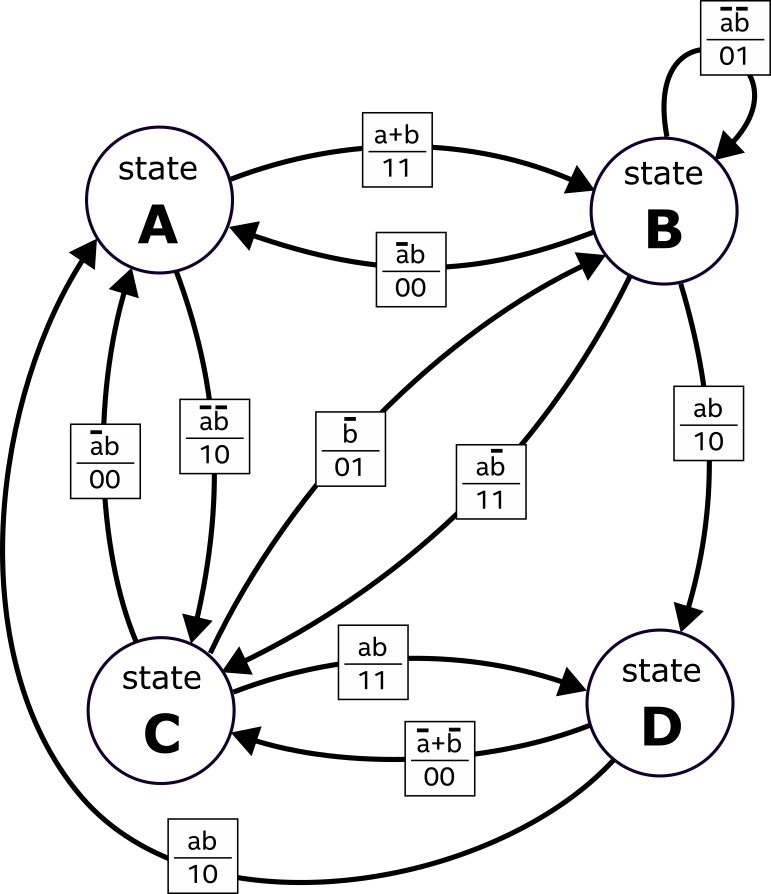
This example state diagram has two inputs: a, b; and two outputs: q1, q0. Negations are (~x), conjunctions (x & y), and disjunctions (x | y). The output values for ports, q1 and q0, are at the end of the if statements
Figure 121. Mealy Machine Code
# Mealy Machine
require version 23.3
inputs a b
netlist
transitions Mealy : q1 q0
    state A
        if (a | b) B 1 1
        if (~a & ~b) C 1 0
    state B
        if (~a & b) A 0 0
        if (~a & ~b) B 0 1
        if (a & ~b) C 1 1
        if (a & b) D 1 0
    state C
        if (~a & b) A 0 0
        if (~b) B 0 1
        if (a & b) D 1 1
    state D
        if (a & b) A 1 0
        if (~b | ~a) C 0 0
end
Figure 122. Moore Machine
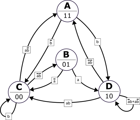
The keyword output indicates the output values for ports, q1 and q0, for each defined state. The condition for the D?D transition, ((~a & b) | (a & ~b)), is equivalent to the exclusive OR, (a ^ b).
Figure 123. Moore Machine Code
# Moore Machine
require version 23.3
inputs a b
netlist
transitions Moore : q1 q0
    moore
    state A
        output 1 1
        if (~b) C
        if (b) D
    state B
        output 0 1
        if (~a) C
        if (a) D
    state C
        output 0 0
        if (a & ~b) A
        if (~a & ~b) B
        if (b) C
    state D
        output 1 0
        if (~a & ~b) A
        if (a & b) C
        if (a ^ b) D
end
ForLoop Blocks
Figure 124. ForLoop Blocks Example
Instantiates a ForLoop block <name> and inequality operator set to <, <=, >, or >=. The values that you specify for <init>, <step>, and <limit> drive the input ports of the ForLoop block.
for <name> <init> <inequality-op> <limit> step <step>: <port-name> ...
 ... nested components
end
If <step> is 1, you can omit it. For example:
for x 0 < 8
end
The port-names are optional. If specified, they must correspond to the names of ForLoop output ports:
| Name | Output Port |
|---|---|
| bs | Body Start |
| ld | Loop Done |
| el | Empty Loop |
| fl | First Loop |
| ll | Last Loop |
| v | Valid |
| c | Counter |
For example:
for x 8 >= 0 step -1 : ld v c
end
Nested ForLoops
You can nest ForLoop blocks.
for x 8 >= 3 step -1
    for y 0 < x

    end
end
for row 0 < 8 : c
    for col 0 < 8 : c v

    end
end
The limits of the inner ForLoop can be the counter value of the outer ForLoop block.
for row 1 < 8 : c
    for col 0 < row : c v

    end
end
Nested ForLoop blocks have the following limitations:
- The ForLoop limits and step size can only be a constant integer or the counter value of an enclosing ForLoop block. DSP Builder does not support arbitrary mathematical expressions (e.g. 2*row+1).
- The Finite State Machine block does not support vector ForLoop blocks
You can also nest state transitions inside ForLoop definitions:
inputs y
netlist
for x 0 < 8
    transitions Simple : q
        state Start
            if (y) Next 1
        state Next
            if (~y) Start 0
    end
end
Unlike when nesting Forloop blocks, state transitions cannot make use of the counter value of the enclosing ForLoop.
To join ForLoop and state transitions in a sequence, declare them one after the other in the configuration file
inputs y
netlist
for x 0 < 8
end
transitions Simple : q
    state Start
        if (y) Next 1
    state Next
        if (~y) Start 0
end
Strategies for Hiding Dead Cycles
DSP Builder holds the valid output (v) of the ForLoop block at zero for at least one cycle whenever the counter is reset to the starting value after it reaches the end limit value. This dead cycle can reduce throughput for designs that use nested ForLoop blocks.
When the outer For-Loop block reinitialises the inner nested ForLoop block, DSP Builder holds the valid out low for one cycle. You can hide this cycle by overlapping it with a valid iteration. You enable the different dead cycle strategies by using the option, dead cycle <strategy>
| Strategy | Description |
|---|---|
| endearly | ForLoop exits one cycle early |
| shiftrange | Outer ForLoop iterations overlaps with first iteration of inner ForLoop. This strategy is limited to ForLoop blocks with constant limits and does not work when the inner ForLoop uses the counter of the outer ForLoop. Supports deeper nesting. |
| oneahead | Outer ForLoop iterations overlaps with first iteration of inner ForLoop. This strategy also works when the inner ForLoop uses the counter of the outer ForLoop. Does not support deeper nesting. |
Figure 125. deadcycle endearly
for row 0 < 8 : c

    deadcycle endearly

    for col 0 < 8 : c v

    end

end
The deadcycle endearly strategy is a simple transformation of the netlist that reduces the number of iterations of the innermost loop by one. The example is functionally equivalent to:
for row 0 < 8 : c

    for col 0 < 7 : c v

    end

end
This strategy only makes sense if the innermost ForLoop body is empty or has zero latency. The one cycle in the outer loop iteration effectively overlaps the final iteration of the inner loop. The control signals also reflect the shortened iteration space such that the last loop and loop done signals go high one cycle earlier. You need to compensate for this behavior in your design.
Figure 126. deadcycle shiftrange
for x 0 < 4

    deadcycle shiftrange


    for y 8 >= 1 step -1

        deadcycle shiftrange


        for z 0 < y : v c

        end

    end

end
The deadcycle shiftrange strategy overlaps each iteration of the outer ForLoop block with the first iteration of the inner ForLoop block. However, in triangular nested iteration, the inner ForLoop needs to access the outer ForLoop block's counter value before it completes its own iteration cycle. To resolve this dependency, the outer ForLoop iterates over the range from (init+step) to (limit+step), i.e. its range shifts forward by one iteration step. This transformation only applies if the outer ForLoop block's parameters are all constants. The following construction does not work:
for x 0 < 4

    for y 8 >= x step -1
        deadcycle shiftrange

        for z 1 < 5
The middle ForLoop block's limit depends on the outer ForLoop block's counter. It is not trivial to shift the range of the y-ForLoop without affecting other ForLoop blocks.
Figure 127. Nested ForLoop Blocks
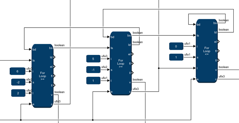
The Finite State Machine block constructs a chain of nested ForLoop blocks as specified by the .fsm configuration file.
Figure 128. Dead CyclesThe valid-out (top) and counter value output (below) for each ForLoop block that the Finite State Machine block builds in its internal netlist: (yellow) The outer ForLoop block, (blue) the middle ForLoop block, and (red) the innermost ForLoop block. The dead-cycles occur when the valid-out from the innermost ForLoop block is low.
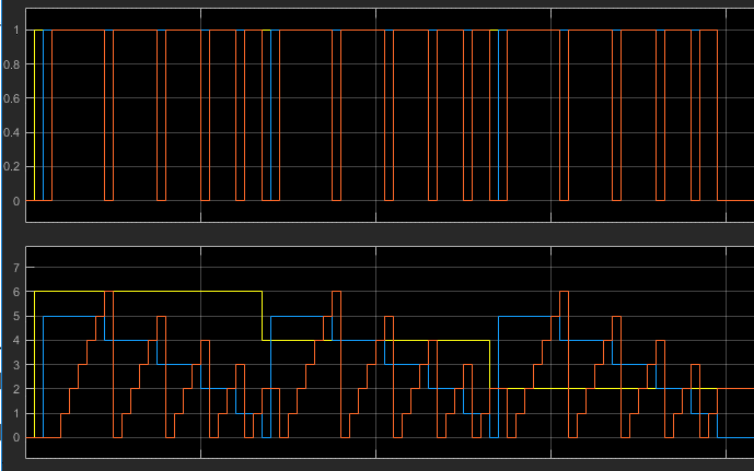
Figure 129. Nested ForLoop Blocks Control LogicFor the shiftrange dead cycle hiding strategy, the Finite State Machine block inserts appropriate control logic between the nested ForLoop blocks to overlap the dead cycle of the inner ForLoop block with a valid iteration of the outer ForLoop block.
Figure 130. No Dead CyclesThe figure shows at the top the valid out of the innermost ForLoop block. At the bottom, the counter value outputs of the three nested ForLoop blocks (yellow: outermost, blue: middle, red: innermost). The valid out stays high until all three ForLoop blocks exit. The Finite State Machine has no dead cycles.
Figure 131. deadcycle oneahead
for x 5 > 1 step -1 : c

    for y 8 >= x step -1

        deadcycle oneahead

        for z 0 <= y : v c


        end

    end

end
The deadcycle_oneahead strategy is similar to the shiftrange strategy but the FSM does not require the inner ForLoop block's parameters to be constants. In the example, the middle ForLoop block's limit is the outer ForLoop block's counter. The netlist transformation uses more elaborate control logic that pre-advances the outer ForLoop by one iteration before initializing the inner ForLoop. This approach doesn't work for deeper nesting structures such as:
for x 5 > 1 step -1 : c

    deadcycle oneahead

    for y 8 >= 1 step -1

        deadcycle oneahead

        for z 0 < y : v c
Although the Finite State Machine hides the dead-cycle in the outer ForLoop, the Finite State Machine inserts an extra cycle to pre-advance the middle ForLoop when applying its dead-cycle hiding strategy.
You can mix and match the different dead-cycle hiding strategies
Section Content
Adding a Finite State Machine Block to your DSP Builder Design
Modifying the Finite State Machine Block Specification File
Implement Token Passing with the Finite State Machine
Implementing a One Shot Counter with the Finite State Machine
Specifying ForLoop Control Units
Creating the Finite State Machine Configuration File
Upgrading Finite State Machine Blocks from v23.2 and Earlier