Visible to Intel only — GUID: qgc1527176992433
Ixiasoft
1. 25G Ethernet Intel® FPGA IP Quick Start Guide
2. 10G/25G Ethernet Single-Channel Design Example for Intel® Stratix® 10 Devices
3. 25G Ethernet Single-Channel Design Example for Intel® Stratix® 10 Devices
4. 25G Ethernet Multi-Channel Design Example for Intel Stratix 10 Devices
5. 25G Ethernet Intel® FPGA IP Design Example References
6. 25G Ethernet Intel® Stratix® 10 FPGA IP Design Example User Guide Archives
7. Document Revision History for the 25G Ethernet Intel® Stratix® 10 FPGA IP Design Example User Guide
1.1. Directory Structure
1.2. Generating the Design Example
1.3. Simulating the 25G Ethernet Intel® FPGA IP Design Example Testbench
1.4. Compiling and Configuring the Design Example in Hardware
1.5. Changing Target Device in Hardware Design Example
1.6. Testing the 25G Ethernet Intel® FPGA IP Design in Hardware
Visible to Intel only — GUID: qgc1527176992433
Ixiasoft
2.6.1. Test Procedure—Design Example Without the IEEE 1588v2 Feature
Follow these steps to test the design examples in hardware using PMA serial loopback:
Note: The design example starts with default data rate of 25G.
- Perform data rate switching to 10G:
- In Intel® Quartus® Prime Pro Edition software, go to Tools > In-System Sources & Probes Editor tool to open the default source and probe GUI.
- Set the source bit[1] in source and probe to 1.
- Perform data rate switching to 25G:
- In Intel® Quartus® Prime Pro Edition software, go to Tools > In-System Sources & Probes Editor tool to open the default source and probe GUI.
- Set the source bit[1] in source and probe to 0.
- Perform system reset release after executing the data rate reconfiguration:
- Click Tools > In-System Sources & Probes Editor tool for the default Source and Probe GUI.
- Toggle the system reset signal (Source[0]) from 0 to 1 to apply the reset and return the system reset signal back to 0 to release the system from the reset state.
- Monitor the Probe signals and ensure that the status is valid.
- Run the following commands in the system console to start the serial loopback test:
Table 7. Command Parameters Parameter Description Example Usage chkphy_status <link num> Displays the clock frequencies and PHY lock status. % chkphy_status 0 # Check status of link 0 chkmac_stats <link num> Displays the values in the MAC statistics counters. % chkmac_stats 1 # Checks mac statistics counter of link 1 clear_all_stats <link num> Clears the IP core statistics counters. % clear_all_stats 1 # Clears statistics counter of link 1 start_gen <link num> Starts the packet generator. % start_gen 1 # Begin packet generation on link 1 stop_gen <link num> Stops the packet generator. % stop_gen 1 # Stop packet generation on link 1 loop_on <link num> Turns on internal serial loopback. % loop_on 2 # Turn on internal loopback on link 2 loop_off <link num> Turns off internal serial loopback. % loop_off 2 # Turn off internal loopback on link 2 reg_read <addr> Returns the IP core register value at <addr>. % reg_read 0x302 # Read IP CSR register at address 302 of link 0 % reg_read 0x4542 # Read transceiver reconfiguration register at address 4542 of link 0
reg_write <addr> <data> Writes <data> to the IP core register at address <addr>. % reg_write 0x30301 0x1 # Write 0x1 to IP CSR scratch register at address 301 of link 3 % reg_write 0x34542 0x0 # Write 0x0 to transceiver reconfiguration register at address 4542 of link 3
Note:- For single-channel design, <link num> is always 0.
- For multi-channel design, <link num> is the channel number. The valid channel number range is 0 to 3.
- Type loop_on <link num> to turn on the internal serial loopback mode.
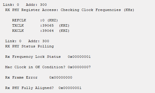
- Type chkphy_status <link num> to check the status of the PHY. The TXCLK, RXCLK, and RX status should have the same values shown below for a stable link:
Figure 11. System Console Example Printout
- Type clear_all_stats <link num> to clear TX and RX statistics registers.
- Type start_gen <link num> to begin packet generation.
- Type stop_gen <link num> to stop packet generation.
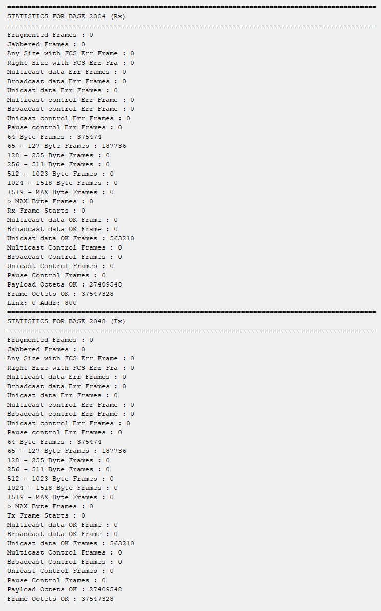
- Type chkmac_stats <link num> to read the TX and RX statistics counters. Make sure that:
- The transmitted packet frames match the received packet frames.
- No error frames are received.
- Type loop_off <link num> to turn off the internal serial loopback.
Note: The above configuration is applied to the default 25G mode for the first time.
Figure 12. Sample Test Output—TX and RX Statistics Counters
Related Information