1.3.4.2. BMS Reference Design uCode Controller Interface
The uCode controller interface configures and controls the matrix processor.
The reference design maps it to an address region in the processor interface. The address map may change based on certain sizes and user -defined parameters of the design.
| Name | Address | Bits | Description |
|---|---|---|---|
| MAT_PROC_OPCODESTART | 0x320 | [4:0] | Line of opCode at which the matrix processor starts uCode execution. |
| MAT_PROC_OPCODESTOP | 0x321 | [4:0] | Line of opCode at which the matrix processor stops uCode execution. |
| MAT_PROC_READY | 0x3B3 | [0:0] | Bit that indicates status of the matrix processor. The host has to test this bit before starting new uCode sequence or to poll for current sequence completion |
| MAT_PROC_GO | 0x3B4 | [0:0] | Bit asserted by host to initiate a uCode sequence execution. Processor has to assert the bit each time to start new execution. |
| MAT_PROC_HOSTACCESS | 0x3B5 | [0:0] | Use this bit to select the user memory multiplex to obtain and release user memory. Assert to obtain access from processor. Deassert to release control to matrix processor. |
In addition, to control registers, the uCode interface has a page with a uCode program stored in internal memory. To configure the matrix pProcessor with your uCode program, fill values into the uCode memory. The depth of the uCode memory is a compile-time parameter.
| Name | Address Line 0 | Bits | Description |
|---|---|---|---|
| MAT_PROC_OPCODE | 0x323 | [3:0] | opCode to execute. |
| MAT_PROC_N | 0x333 | [3:0] | N size parameter of the opCode. |
| MAT_PROC_M | 0x343 | [3:0] | M size parameter of the opCode. |
| MAT_PROC_W | 0x353 | [3:0] | W size parameter of the opCode. |
| MAT_PROC_ARG1 | 0x363 | [31:0] | Arg1 parameter of the opCode Bits [8:0] Argument1 offset Bits[31:28] Argument 1 extension |
| MAT_PROC_ARG2 | 0x373 | [31:0] | Arg2 parameter of the opCode Bits [8:0] Argument2 offset Bits[31:28] Argument 4 extension |
| MAT_PROC_ARG3 | 0x383 | [31:0] | Arg3 parameter of the opCode Bits [8:0] Argument3 offset Bits[31:28] Argument 4 extension |
| MAT_PROC_ARG4 | 0x393 | [31:0] | Arg4 parameter of the opCode Bits [8:0] Argument4 offset Bits[31:28] Argument 4 extension |
| MAT_PROC_ARG5 | 0x3A3 | [31:0] | Arg5 parameter of the opCode Bits [8:0] Argument5 offset |
To configure the matrix processor to execute an algorithm, the CPU host must program it. To program, fill data into the uCode program area and provide run-time configuration parameters.
| Name | Valid Entries | Description |
|---|---|---|
| MAT_PROC_OPCODE | 1, 3, 4 | Operation mode: 1 – D + C * A-1 * B 3 – A * B 4 – A * B + C |
| MAT_PROC_N | 2-MAX | N size parameter of the opCode MAX is compile time parameter |
| MAT_PROC_M | 1-MAX | M size parameter of the opCode MAX is compile time parameter |
| MAT_PROC_W | 1-MAX | W size parameter of the opCode MAX is compile time parameter |
| MAT_PROC_ARG1 – Matrix A MAT_PROC_ARG2 – Matrix B MAT_PROC_ARG3 – Matrix C MAT_PROC_ARG4 – Matrix D |
XXX | Arg1 to Arg4 parameter of the opCode Bits [8:0] Argument offset Bits[31:28] Argument extension [30:28] Valid when opCode = 1 0 – Normal (no data manipulation) 1 – Negate elements 2 – Zero elements Matrix 3 – Identity matrix 4 – Negative identity matrix [31] 0 – Do not transpose matrix 1 – Transpose matrix |
| MAT_PROC_ARG5 | XXX | Result matrix Arg5 parameter of the opCode Bits [8:0] Argument5 offset |
In the matrix processor solution, the reference design accelerates part of the matrix operation using the matrix processor. Meanwhile, the Nios II processor can also be doing calculations.
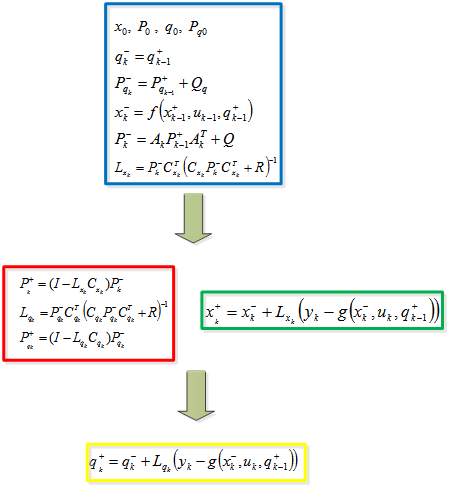
Figure 23. Task SchedulingThe Nios II processor calculates the steps in the blue box. Then the matrix processor starts calculating the equations in the red box. Meanwhile, the Nios II processor can process the steps in the green box. Finally, the Nios II processor finishes the calculation in the yellow box.