Visible to Intel only — GUID: tpi1534354317849
Ixiasoft
2.3.5. PCB Post-Layout Simulation Phase
Post-layout simulation is a mandatory design phase for the Intel® Stratix® 10 E-Tile high-speed data links. Follow the steps below in your post-layout simulation:
- Pick three or more pairs of channels with the worst via coupling for s-parameter extraction for the impedance and crosstalk validation.
- Perform time-domain channel eye simulation with the IBIS-AMI models while the actual channel model is being extracted.
Strategy for Post-Layout PCB Channel Modeling
- Extract the entire PCB channel in the E/M solver (not recommended)
- The extraction takes a long time to finish and is not even possible for many complicated cases.
- Connector pads do not have proper coupling to the connector, and may be double-counted when cascading with the connector model.
- Use the divide-and-conquer method (recommended)
- Cut the channel at the trace near the FPGA/connector pad/via boundary.
- Solve the trace-only portion.
- Solve the FPGA via with the package ball and ground reference.
- Solve the connector pad/via with the connector together. This step may require SI support from the connector vendor.
- Cascade all pieces solved individually to build the whole channel eye simulation with the IBIS-AMI model.
The following figure shows a channel model extraction example using the recommended procedure, i.e. the divide-and-conquer methodology.
Figure 25. Divide and Conquer Methodology in Channel Model Extraction
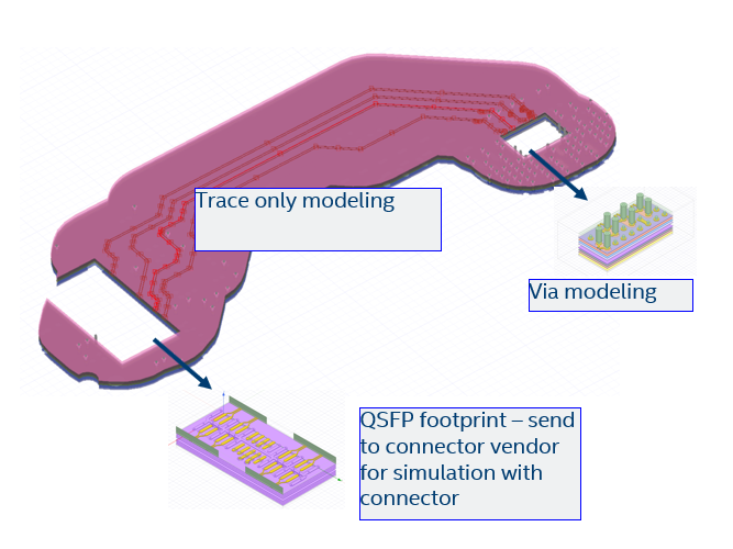
This figure shows a group of four RX channels selected from the actual layout of a PCB. The benefits of the divide-and-conquer methodology to this example are:
- No double counting of the QSFP pin pads when combining with the QSFP connector model.
- The different portions of the channel can be simulated faster individually, and these simulations can be run in parallel.
- A 2.5D E/M solver may be good enough for trace-only geometries.
- Trace setup is easier and includes the etching effect.
The only disadvantage of the divide-and-conquer method is that it takes a longer time to prepare the cutouts and settings. However, the time cost can be improved with clearly specified steps.