Visible to Intel only — GUID: myq1529450472293
Ixiasoft
5.3.1. The Configure Menu
5.3.2. The System Info Tab
5.3.3. The GPIO Tab
User DIP Switches
User LEDs
User Push Buttons
Qsys Memory Map
5.3.4. The EPCQ Tab
5.3.5. The FMC+ Tab
5.3.6. The PAM4 Tab
5.3.7. The MXP Tab
5.3.8. The QSFPDD1x2 Tab
5.3.9. The QSFPDD2x1 Tab
5.3.10. Power Monitor
5.3.11. Clock Controller
Visible to Intel only — GUID: myq1529450472293
Ixiasoft
5.3.3. The GPIO Tab
The GPIO Tab allows you to interact with all the genral purpose user I/O components on your board. You can read DIP switch settings, turn LEDs on or off and detect push button presses.
Figure 16. The GPIO Tab
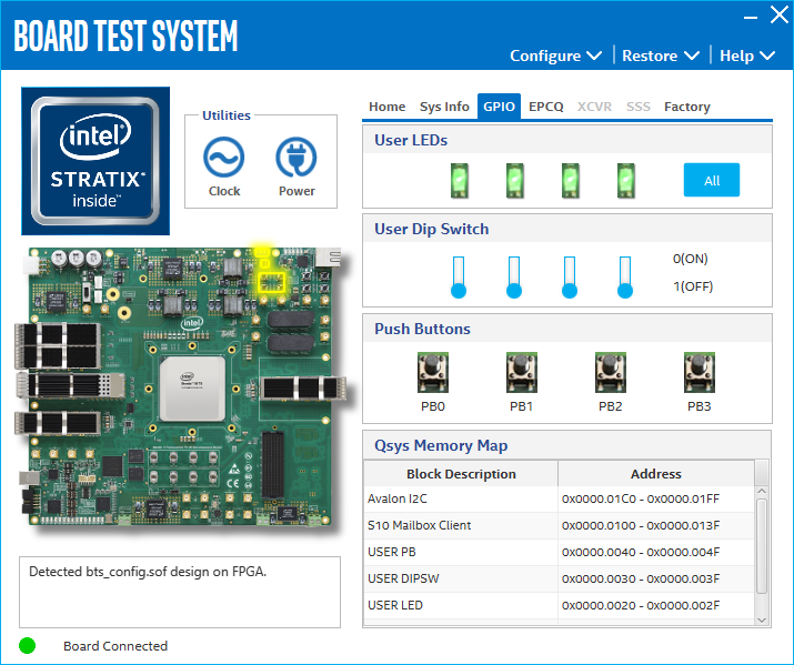
The following sections describe the controls on the GPIO tab.
User DIP Switches
The read-only User DIP switches control displays the current positions of the switches in the user DIP switch bank (SW4). Change the switches on the board to see the graphical display change.
User LEDs
The User LEDs control displays the current state of the user LEDs. Toggle the LED buttons to turn the board LEDs on and off.
User Push Buttons
The read-only User Push Button control displays the current status of the push buttons. Press the push button on the board to see the graphical display change.
Qsys Memory Map
Shows the memory map of the GPIO/FLASH Qsys system on yor board.