Visible to Intel only — GUID: kwc1529450702797
Ixiasoft
5.3.1. The Configure Menu
5.3.2. The System Info Tab
5.3.3. The GPIO Tab
5.3.4. The EPCQ Tab
5.3.5. The FMC+ Tab
5.3.6. The PAM4 Tab
Status
Port
PMA Setting
Data Type
Error Control
Run Control
5.3.7. The MXP Tab
5.3.8. The QSFPDD1x2 Tab
5.3.9. The QSFPDD2x1 Tab
5.3.10. Power Monitor
5.3.11. Clock Controller
Visible to Intel only — GUID: kwc1529450702797
Ixiasoft
5.3.6. The PAM4 Tab
The PAM4 tab allows you to perform loopback tests on the SMAA, SMAB, QSFPDD1x1A and QSFPDD1x1B port. Install QSFPDD loopback module and cable for QSFPDD1x1 and 2.4 mm Rf connectors, configure FPGA with PAM4 image.
Figure 19. The PAM4 Tab
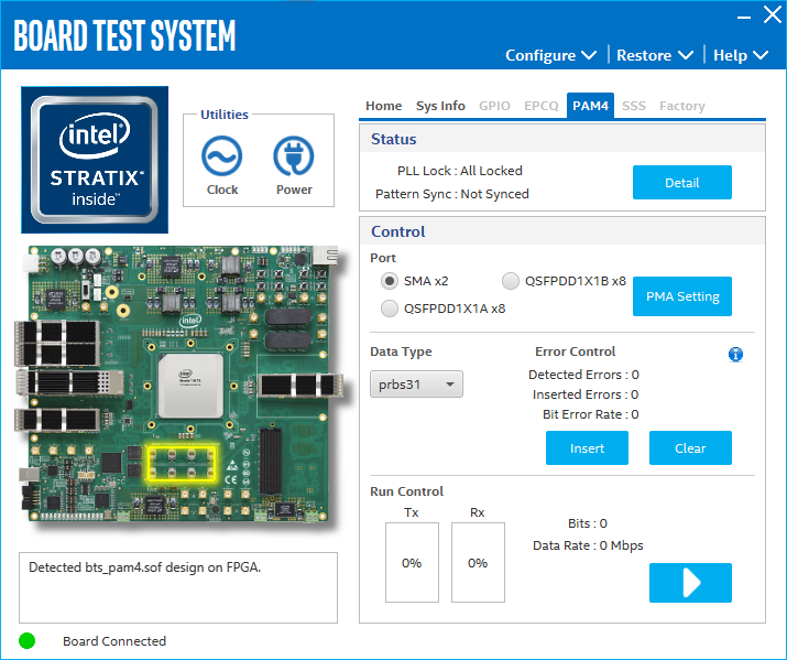
The following sections describe the controls on the PAM4 tab.
Status
Displays the following status information during a loopback test:
- PLL Lock: Shows the PLL locked or unlocked state.
- Pattern Sync: Shows the pattern synced or not synced state. The pattern is considered synced when the start of the data sequence is detected.
- Details: Shows the details of PLL lock, pattern status and error bits of each channel.
Figure 20. SMA Status

Figure 21. QSFPDD1X1 Status

Port
Allows you to specify which interface to test. The following port tests are available: SMAx2, OSFPx8 and QSFPDDx8.
PMA Setting
Allows you to make changes to the PMA parameters that affect the active transceiver interface. The following settings are available for analysis:
- Serial Loopback: Routes signals between the transmitter and the receiver.
- VOD: Specifies the voltage output differential of the transmitter buffer.
- Pre-emphasis tap:
- Pre-tap 1: Specifies the amount of pre-emphasis on the first pre-tap of the transmitter buffer.
- Pre-tap 2: Specifies the amount of pre-emphasis on the second pre-tap of the transmitter buffer.
- Pre-tap 3: Specifies the amount of pre-emphasis on the third pre-tap of the transmitter buffer.
- Post-tap 1: Specifies the amount of pre-emphasis on the first post-tap of the transmitter buffer.
- Equalizer: Specifies the RX tuning mode for receiver equalizer.
Figure 22. SMA PMA Setting

Figure 23. QSFPDD1X1 PMA Setting

Data Type
Specifies the type of data contained in the transactions. The following data types are available for analysis.
- PRBS 7: Selects pseudo-random 7-bit sequences.
- PRBS 9: Selects pseudo-random 9-bit sequences.
- PRBS 11: Selects pseudo-random 11-bit sequences.
- PRBS 15: Selects pseudo-random 15-bit sequences.
- PRBS 23: Selects pseudo-random 23-bit sequences.
- PRBS 31: Selects pseudo-random 31-bit sequences.
Error Control
Displays data errors detected during analysis and allows you to insert errors:
- Detected Errors: Displays the number of data errors detected in the hardware.
- Inserted Errors: Displays the number of errors inserted into the transmit data stream.
- Bit Error Rate: Displays the error rate of data transaction.
- Insert: Inserts a one-word error into the transmit data stream each time you click the button. Insert is enabled only during transaction performance analysis.
- Clear: Resets the Detected errors and Inserted errors counters to zeroes.
Run Control
TX and RX performance bars: Show the percentage of maximum theoretical data rate that the requested transactions are able to achieve.
Start: This toggle button initiates and stops the tests.
Tx (Mbps) and Rx (Mbps): Show the number of bytes of data analyzed per second.