Visible to Intel only — GUID: joc1463027536138
Ixiasoft
Intel® Stratix® 10 Devices and Transceiver Channels
PCB Stackup Selection Guideline
Recommendations for High Speed Signal PCB Routing
FPGA Fan-out Region Design
CFP2/CFP4 Connector Board Layout Design Guideline
QSFP+/zSFP/QSFP28 Connector Board Layout Design Guideline
SMA 2.4-mm Layout Design Guideline
Tyco/Amphenol Interlaken Connector Design Guideline
Electrical Specifications
Document Revision History for AN 766: Intel® Stratix® 10 Devices, High Speed Signal Interface Layout Design Guideline
Option 1: Via-In-Pad Topology
Option 2: Dog-bone with GND Cutout at BGA Pad Topology
Option 3: Micro-via Topology
GND Cutout Under BGA Pads in Fan-out Configuration
Comparison of Dog-bone with GND Cutout Under the BGA and Via-in-Pad Configurations
Trace Shape Routing at the BGA Void Area (Tear Drop Configuration)
Visible to Intel only — GUID: joc1463027536138
Ixiasoft
Comparison of Dog-bone with GND Cutout Under the BGA and Via-in-Pad Configurations
Figure 10. Comparison of TDR from the FPGA Pad of Via-in-Pad and Dog-bone ConfigurationsThe pink line indicates the dog-bone configuration and the green line indicates the via-in-pad configuration.
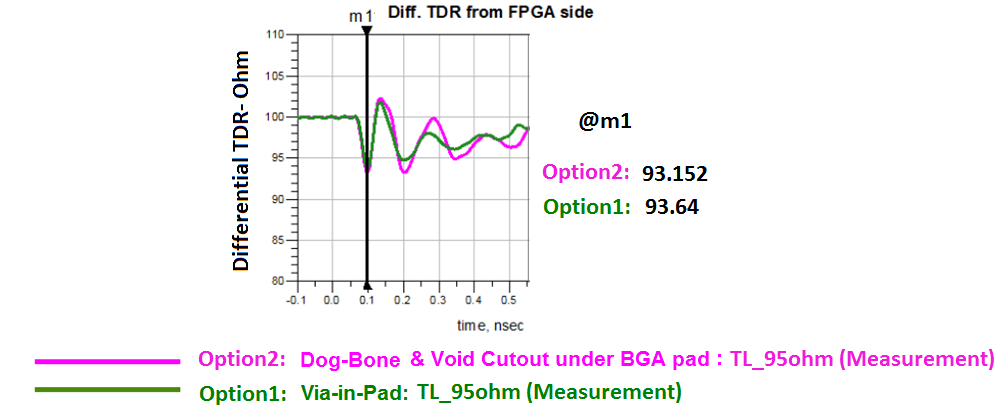
In terms of TDR, both configurations have similar performance.
Figure 11. Full channel scattering parameter performances for Dog-Bone Configuration with GND/Void cutout underneath of BGA (Option 2) vs Via-in-pad (Option 1) ConfigurationsFigure shows the identical channel but uses the via-in-pad or dog-bone configuration in the FPGA area.

Note:
- Option 1 (Green): Via-in-pad.
- Option 2 (Pink): Dog-bone with GND/Void cutout under BGA pad configuration.
In this example, the via-in-pad shows slightly better performance. The other advantage of via-in-pad is that it provides more space for fan-out routing.
Figure 12. TDR Performance and TL Impedance ImpactThe example uses a dog-bone fan-out configuration and one layer GND cutout under the BGA pad by various TL routing impedances.
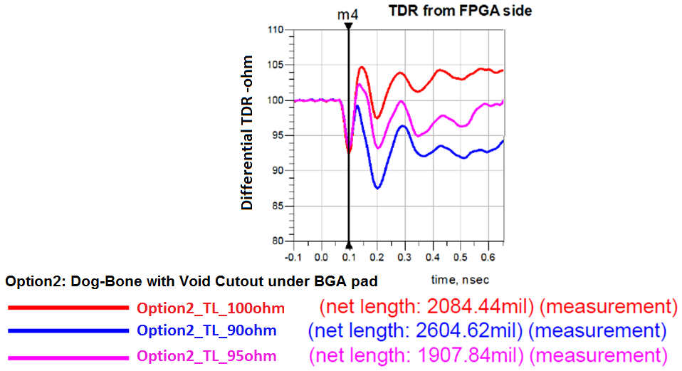
This example shows that slightly lowering the TL routing impedance ensures a smoother transition from the BGA pad, which results in less reflection on the channel. Intel recommends a 95Ω TL routing impedance for high speed serial interface (HSSI) channels.