Visible to Intel only — GUID: joc1463008729855
Ixiasoft
Intel® Stratix® 10 Devices and Transceiver Channels
PCB Stackup Selection Guideline
Recommendations for High Speed Signal PCB Routing
FPGA Fan-out Region Design
CFP2/CFP4 Connector Board Layout Design Guideline
QSFP+/zSFP/QSFP28 Connector Board Layout Design Guideline
SMA 2.4-mm Layout Design Guideline
Tyco/Amphenol Interlaken Connector Design Guideline
Electrical Specifications
Document Revision History for AN 766: Intel® Stratix® 10 Devices, High Speed Signal Interface Layout Design Guideline
Option 1: Via-In-Pad Topology
Option 2: Dog-bone with GND Cutout at BGA Pad Topology
Option 3: Micro-via Topology
GND Cutout Under BGA Pads in Fan-out Configuration
Comparison of Dog-bone with GND Cutout Under the BGA and Via-in-Pad Configurations
Trace Shape Routing at the BGA Void Area (Tear Drop Configuration)
Visible to Intel only — GUID: joc1463008729855
Ixiasoft
GND Cutout Under BGA Pads in Fan-out Configuration
If you use the dog-bone fan-out configuration, Intel recommends that you have one GND reference plane cutout under the BGA pad to reduce capacitance in this area. Larger GND cutouts provide better impedance transition at the fan-out; however, the GND cutout in the fan-out is limited due to limited routing space.
Figure 7. Conventional Dog-bone and Recommended Dog-bone ComparisonOriginal design without a GND cutout under the BGA pad and with cutout.
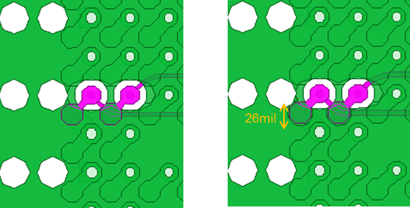
Note: The cutout is 26 mil in diameter as socket is used for this device. If socket is not used, Intel recommends 22 mil.
Figure 8. TDR Simulated Performances of the Entire Channel with Magnified FPGA BGA AreaDesign uses 100 Ω and 90 Ω differential impedance routing.
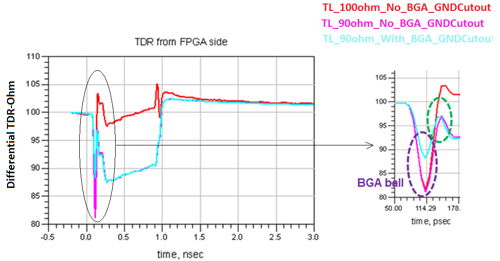
TL impedance impact effect with dog-bone fan-out configuration and with/without GND cutout underneath of BGA pad is approximately 10 Ω based on TDR performance in Figure 8.
Figure 9. Simulated Performances of Insertion and Return LossFull channel simulation uses 100 Ω and 90 Ω differential impedance routing.
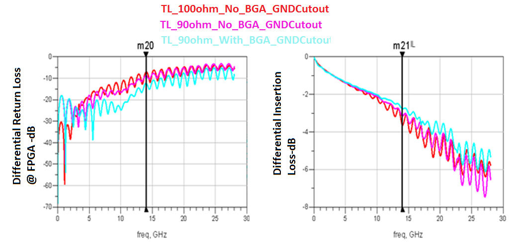
The red line indicates the original design and 100 Ω TL routing impedance.
The pink line indicates the original design and 90 Ω TL routing impedance.
The blue line indicates the original design with 26 mil diameter GND cutout under the BGA pad and 90 Ω TL routing impedance.
The improvement on insertion loss is 1 dB and approximately 5 dB on return loss at 14 GHz.